Once the design is complete and all of the consents are in place the final stage of the project is construction. One of the strengths of Renewables First is that we don’t just consult and design, we build systems as well. It is only through the construction of hydropower systems that you truly learn the subtleties of good hydropower design.
We have a reliable team of sub-contractors that assist us during the installation phase while Renewables First provide the project management expertise and supervision during key project stages, as well as our own staff that specialise in turbine set-up and system commissioning.
The following pictures show a typical construction sequence, over six months, from site preparation, construction of the structures, installation of the turbine, generator and electrical system and commissioning. For more detail the picture thumbnails can be expanded by clicking them, then use the ‘back’ button in your browser to return to this page.
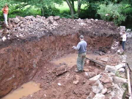
Most projects start with large excavations, as shown here. The main reason for including this picture is to give you an idea of the scale of the project, even for a relatively small hydropower system. We will damage the lawn!
 micro-hydro-turbine-installation-process-1 |
Most projects start with large excavations, as shown here. The main reason for including this picture is to give you an idea of the scale of the project, even for a relatively small hydropower system. We will damage the lawn! |
 2-Micro-hydro-Turbine-generator-install |
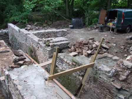
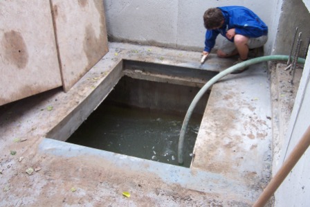
Some sites have existing historical infrastructure. This picture shows the old bypass sluice channel walls being rebuilt ready for installation of a new sluice and elver-pass before the new turbine house and intake and discharge channels are constructed. |
 3-Micro-hydro-Turbine-generator-install |
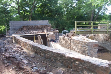
The intake channel and turbine house mid-way through construction. The turbine house is made up of a waterproof cast-concrete tank, which will remain watertight even in extreme flood events. Above worst-case floodwater level the walls change to concrete block inner and local stone outer. |
 4-Micro-hydro-Turbine-generator-install |
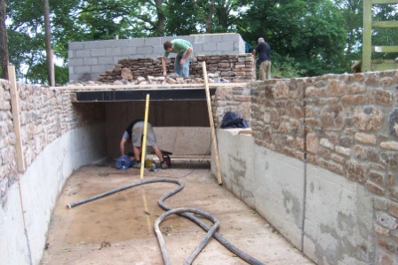
The intake channel which conveys water from the river to the intake screen which will be located just in front of the opening that is visible. The intake channel should be large to minimise water velocities and ‘head’ loss, and maximise power output. |
 5-Micro-hydro-Turbine-generator-install |
The end of the intake channel at the intake screen location. The hole in the turbine house wall will later have the turbine intake adaptor fitted into it, then concreted in place to make it watertight. |
 6-Micro-hydro-Turbine-generator-installation |
The view from inside the turbine house looking through the hole for the turbine intake adaptor and down the intake channel. |
 7-Micro-hydro-Turbine-generator-install |
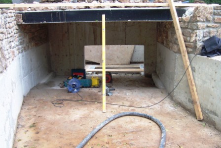
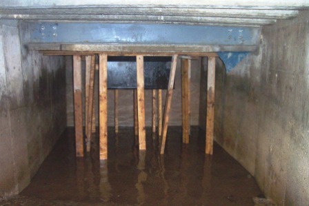
This picture shows the space that the turbine will occupy. The water will enter from the right, turn through 90° inside the turbine, then discharge through the hole in the floor into the discharge sump underneath. Once the turbine is installed the whole area will be watertight, with no visible water. |
 8-Micro-hydro-Turbine-generator-install |
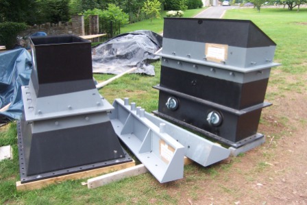
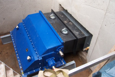
The turbine inlet adaptor on the right (goes between the turbine and the intake screen) and the draft tube on the left (discharges the water from the turbine into the discharge sump). Both of these parts get concreted into the turbine house structure to ensure the turbine house stays watertight. |
 9-Micro-hydro-Turbine-generator-install |
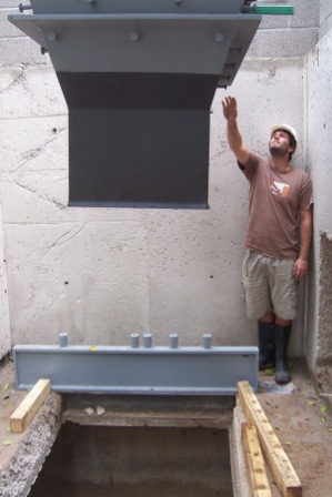
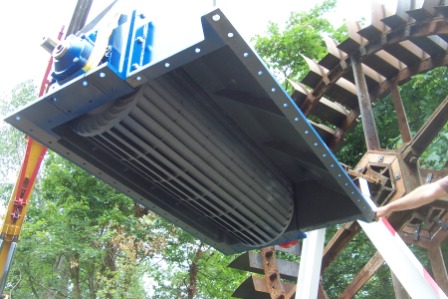
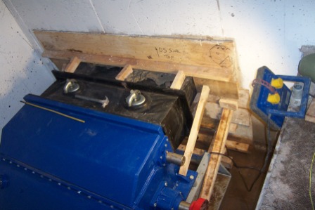
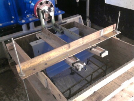
The draft tube being lowered into position. The ‘pegs’ that stick out above and below the flange at the top of the photo are keys for anchoring the draft tube into the concrete when it is finally fixed in place. |
 10-Micro-hydro-Turbine-generator-install |
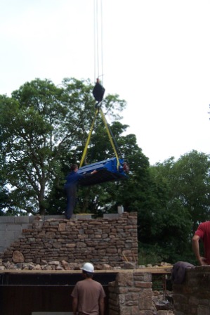
The turbine body being lowered into position. The underside of the turbine bolts to the top of the draft tube. |
 11-Micro-hydro-Turbine-generator-install |
The turbine being lowered into position, viewed from below. The crossflow runner can be clearly seen, along with its Victorian ancestor behind! |
 12-Micro-hydro-Turbine-generator-install |
The turbine sitting on its supports. The draft tube can just be seen underneath, before the gasket is fitted and it is jacked-up from below to mate with the turbine and be bolted together. |
 13-Micro-hydro-Turbine-generator-install |
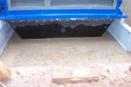
The draft tube bolted to the turbine, then the hole in the turbine house floor has been concreted to seal it. The first 2 metres of vertical wall around the turbine, along with the floor, form a concrete ‘tank’ that prevents flood water entering the turbine chamber during extreme flood events (which happen a least once a year at this low-head site). |
 14-Micro-hydro-Turbine-generator-install |
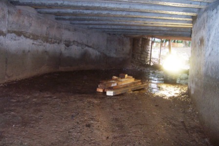
The timber supports holding up the formwork used when concreting the draft tube into position. This is the turbine discharge sump, which receives the discharged water from the turbine once all of the energy has been extracted, before returning the water to the river. |
 15-Micro-hydro-Turbine-generator-install |
Taken from the discharge sump, looking down the tailrace tunnel with the river at the end. |
 16-small-hydro-turbine-generator |
The inlet adaptor being fitted to the turbine. The long white strips are PTFE gasket tape that ensure the joint is leak-free. |
 17-small-hydro-turbine-generator |
The inlet adaptor fitted, prior to being concreted into position. |
 18-small-hydro-turbine-generator |
Shuttering and concreting the inlet adaptor into position; the final hole blocked-up to make the turbine tank waterproof. |
 19-small-hydro-turbine-generator |
Casting the concrete block that the gearbox and generator will sit on. |
 20-small-hydro-turbine-generator |
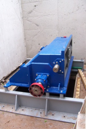
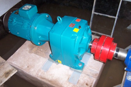
The generator, gearbox and coupling assembled and connected to the turbine shaft. This converts the mechanical energy from the turbine into electricity. |
 21-micro-hydro-power |
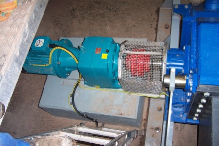
The generator wired-up and the drive guard fitted. |
 22-micro-hydro-power |
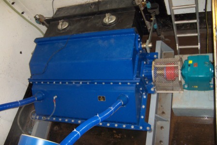
The crossflow turbine, gearbox and generator all installed. |
 23-micro-hydro-power |
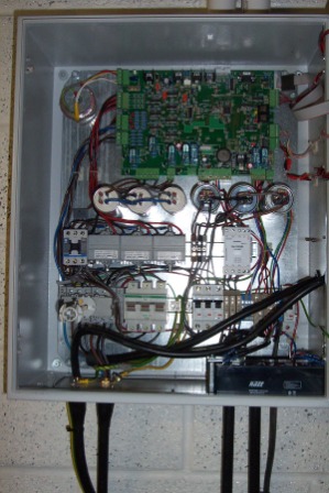
Inside the hydro system controller (also the grid connection controller). The wires go to the intake water level sensor, the turbine inlet actuators (to adjust the water flow through the turbine), from the generator and out to the main building electrical system. |
 24-micro-hydro-power |
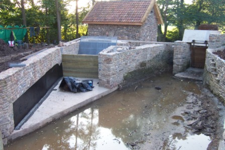
The upstream-side of the hydro system, just prior to the coffer-dam being removed and the area being refilled with water for the first time. |
 25-micro-hydro-power |
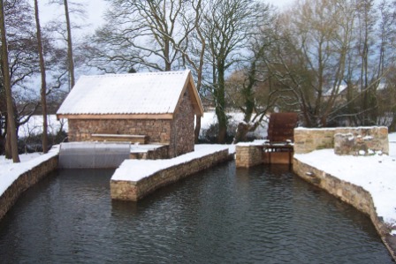
The snow of January ’09 didn’t affect the quiet and reliable operation of the hydro system. |
This project demonstrates the continuing viability of traditional water mills which, used appropriately, can mill flour more cheaply than the diesel mills which are threatening to replace them. The increase in income from an upgraded mill is such that the investment can be paid back in about a year – an excellent rate of return, which bodes well for the rapid expansion of the model across the region.
The Eastern Africa office in Kenya has installed very small ‘pico-hydro’ power systems for two remote communities on the slopes of Mount Kenya.
These projects provide over 200 homes with lights and power points. As well as giving light to study by and power to recharge appliances like radios, the electricity also opens up new income-generating possibilities to villagers, from chicken farming to charging points for mobile phones – a social and economic lifeline to health workers, family and markets elsewhere.
The schemes’ size and design avoid environmental disruption while providing a cheaper and safer alternative to kerosene and lead-based dry cells. Equally important is ITDG’s success in bringing about a proposed change of policy in Kenya to help create a decentralized electricity market, allowing micro-schemes such as these to thrive countrywide.