micro hydro power China

what is hydro power
Power is voltage X current and is expressed in watts or KW. The K in KW is 1000 watts
Current is measured in “amps” so Power can be expressed as Volts X Amps
If we take 110 volts X 1 Amp we have 110 Watts
E is often used in the place of the word ‘volts’
I is often used in the place of the word ‘current
how to save electric bill

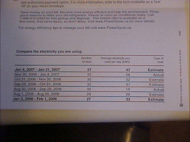
calculations_based_on_your_bill
To start with we want to get an average of the power consumed.
To do this we will add the numbers in the “Average electricity you used per day (KWH)”
42+58+32+31+15+29+33=240
Next we want to divide this by the amount of numbers in this case 7
240/7=34.28 or we can round it to 34
With this number we now have the average KWH per day over the last 7 months
•34 KWH used per day now must be converted to KWH/H and since there is 24 hours in a day we need to divide 34/24 hours =1.4166
•Now we need to multiply this number by 1000 to convert it to watts/h so we end up with 1416.6 watts per hour.
So to make things simple we need a 1500 watt generator to meet the needs of this consumer.

Battery_bank_calculations
A really good battery will have 130AH rating but what does this mean?
130AH is really 130 amps at 0 volts for 1 hour. Since a conventional battery is 12 volts, lets use that for the purpose of this explanation.
Divide 130 AH by 12 volts to get the amps per hour and we get 10.833 amps for 1 hour. Therefore one fully charged 130AH battery will give us 10.833 amps at 12 volts for one hour.
From above we saw that we could get 10.833 amps for one hour at 12 volts. To convert this to watts we multiply the volts x the amps to get watts therefore 10.833 amps x 12 volts is 130 watts/hour. From our electrical bill we can see that we need 1500 watts per hour so we will need to have 1500/130 =11.53 batteries for each hour that we want power – provided we don’t have a way to charge the battery while we are drawing from it. Since we want to maximize battery life and shouldn’t discharge a battery more than 30% we will need about 33 batteries.

hydro electric basics
•Power Output and Site Parameters
•To determine the power that can be used at your site you must know the flow and the head. The flow is the rate at which water moves in the stream, measured in gallons per minute (gpm) or litres per second (l/s). This can be determined by channeling the water into a pipe, then into a container of known volume and noting how much time it takes to fill. The head is the vertical distance the water travels. This can be measured with a transit or by sitting along a level. Another technique uses a length of pipe filled with water and a pressure gauge attached to the end. Also a transparent hose can be filled with water and used as a level. Use the hose to measure one section of of the stream at a time.
•Once the head and flow are known, an approximate estimate can be made from the following formula:
•Head (feet) x Flow (gpm) / 10 = Watts [For example, 100 feet x 30 gpm / 10 = 300 watts]
•Before considering the purchase of a Hydro Electric setup, perform the above estimate. If your site has adequate potential output, contact us to discuss these other site parameters:
•Pipeline or Penstock: The length, diameter, and type of pipe must be determined to predict losses due to friction.
•Transmission Distance: This affects the generation voltage and type required and wire size needed to keep losses acceptable.
•System Voltage: Many factors affect voltage, such as system capacity and transmission distance. Power is usually generated at battery voltage. Where transmission distances are too great, higher voltages can be generated and transformers effectively used to step down battery voltage.

flow rate by distance
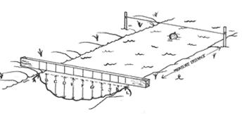
flow rate by distance

flow rate by container fill method
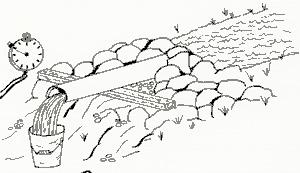
hydro power flow rate container
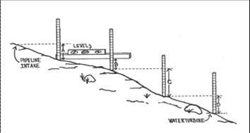
pic micro hydro power measuring head
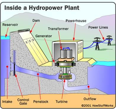
inside hydro power station

component of a micro hydro system: intake
Assuring clean water as your source for power is rather important. Some creeks have a lot of leaf or other debris, some may be shallow and sandy. Running a turbine without a filter for even a short time could suck in material which could settle in your pipe or block your jet. A blocked jet can cause water hammer which could damage your installation. Therefore your intake filter is important. A larger filter with lots of holes is not so likely to suck in debris or cause a swirling eddy which pulls in debris. Vortex action may be worsened if it is too close to the surface and if too close to the bottom it may suck in sediment. Make filters out of material which won’t corrode. The area of all the holes in total should be at least 10 times the diameter area of the pipe. The diameter of each filter hole should be less than the smallest nozzle or jet you plan to use on the turbine. If your turbine does not initially perform as expected we suggest you remove the filter temporarily to see if this makes a difference. If it does, you need a larger filter or more holes in it. Use your imagination

component of a micro hydro system: penstock
Penstock measurement is easy. Simply run a tape measure between your intake and turbine locations, following the route you’ll use for your pipeline. The penstock or pipe line is often made of plastic – either PVC or polyethylene. PVC pipe should be buried for protection from the sun’s ultraviolet rays, polyethylene & cast iron should be buried for protection from falling trees, rocks or machines. Also, if air temperatures normally stay below -5C for more than five days at a time, the pipeline should be buried or insulated.
Head Loss refers to the loss of water power due to friction within the penstock. Although a pipe diameter may be enough to carry all the water flow in the design – the pipe sides, joints and bends create drag as the water passes, therefore slowing it down and effectively lowering the Head and resulting in less water pressure at the turbine. The effects of head loss can only be measured when water is flowing. Larger pipes are less friction but add more cost.
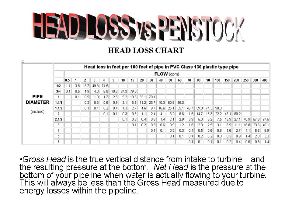
water head loss chart

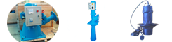
components of a micro hydro system: generator
Turbine generator units are available from a number of sources. The choice of unit depends on a number of factors such as power line distance, desired equipment reliability, desired voltage and/or current type and cost. Power can be generated as AC or DC but DC has increased line loss and installation expense. In a typical situation where periodic inspection and minor maintenance is possible, the alternator system is most common. Electricity can be fed directly to the grid or stored in your own battery bank. The user is free to make changes to the turbine nozzle size to suit power requirements and or flow conditions.
components of a micro hydro system: battery
The size of the battery bank is determined by the anticipated loads, the available charging power and the budget. A small bank might consist of one deep cycle battery or 1 or 2 car batteries with a capacity in the range of 200 amp hours providing sufficient power for a small weekend cabin while a large installation may be made up of 12 six volt cells wired to produce 12 or 24 volts with a capacity of over 1000 amp hours.
Deep cycle batteries have been central to DC power systems and store energy for periodic surges and long term draw needed by various electrical loads. Automobile batteries have been used also but more may be required. TAP Green Batteries are now available. They have faster recharging times, high storage capacity, longer life, no toxic gas production and no lead/acid concerns – to name a few of the environmentally positive attributes.
component of a micro hydro system: charge controller
Control and monitoring of battery voltage is important to prevent damage from over charging or from accidental discharge. The monitoring equipment consists of indicator meters or lights to inform the user of system status, and the control unit maintains an optimum voltage on the battery by either regulating the generator output or by shunting power to alternate loads such as heating domestic hot water.
components of a micro hydro system:inverter
Powerful DC to AC inverters are used to produce high quality 110 volt AC directly from the battery bank. These units are available in sizes from 125 watts up to 5000 watts and operate at over 90 percent efficiency. They are fully protected against any abnormal operating conditions and take virtually no power when in an idle mode.

hydro power turbine types
There are many types of turbines to choose from and we will show you a few of them as well as a bit of their history and development. Your choice of turbine will depend on your water source as well as other factors discussed here.
The types of hydroelectric turbines are divided into 2 distinct groups: IMPULSE and REACTION. The runners of Impulse turbines are not immersed in water. Water flows onto the tabs that make up the runner therefore making it move. Reaction turbines have the runner completely immersed in water, which flows between the vanes therefore moving the drive shaft

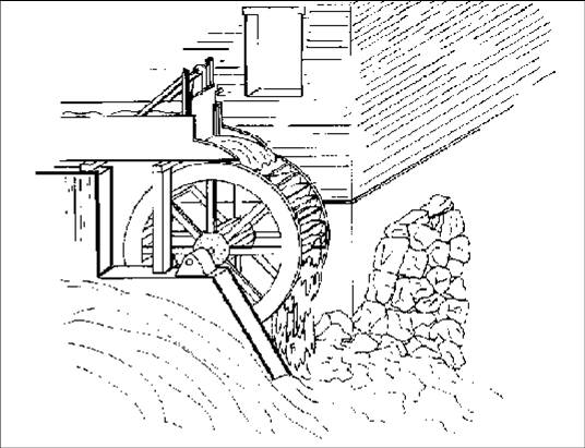
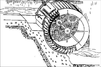
overshot and undershot water wheels
The names indicate the point at which the water enters the wheel. If you face the water wheel from the side and regard it as a clock face, then the overshot would revolve in a clockwise direction while the pitch-back, the breast shot and undershot water wheels revolve in an counterclockwise direction.
The overshot wheel is the most common wheel seen in North America. It is a gravity wheel. This means that it harnesses the force of gravity acting vertically on the water as it travels from the top to the bottom of the wheel. Properly designed for the site, and correctly timed, an overshot wheel can slow the natural velocity of the falling water to as little as 10% of what it would be if the wheel was not there.
An undershot water wheel is an impulse wheel as it pushes the water. If a hillside is steep, the water moves fast at the bottom and can push strongly against the paddles of an undershot wheel.
The average overshot wheel was far more efficient than the undershot, about 65% as opposed to 25%.
overshot wheel

breast wheel
breast whell

pelton hydro turbine
The original and classic microhydro turbine design is the Pelton. Invented in the 19th century by directing water jets used in hydraulic mining onto overshot water wheels, it provided a way to get the high rotating speeds necessary for electrical generation.
It is used for low flow battery-charging systems, where the head is over 30 feet or so. It requires at least ten feet of head.
pelton wheel

turgo turbine
The Turgo runner is a refinement of the Pelton, where the jets direct water at the runner at an angle. The Turgo is used especially for situations with high water flows; the design allows for larger jets. Because Turgos can use more water, significant power can be generated with less head, this results in shorter penstocks
•In addition the Turgo is rugged and can be used as a small and inexpensive turbine for the right kind of site, making it a commonly used turbine.
The Turgo turbine runner

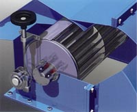
cross flow hydro turbine generator
BANKI
It is also called CROSS-FLOW and it is an impulse two-stage turbine. Water goes into the turbine via a distribution system and it arrives at a first stage of the rotor functioning almost totally submerged. Subsequently, the water flow changes direction and reaches the second stage of the turbine, which is totally an impulse stage.
The rotor of the turbine is formed by parallel disks, among which the blades are installed, characterized by bent tongues. The form of the rotor is similar to the one of a tangential ventilation system. The easy construction of the turbine allows to produce it in developing countries too. The efficiency of this turbine is less than 87%, keeping almost constant till low flow rates (>16%).
BANKI turbines are used for water heads from 5 to 200m.
banki-turbine

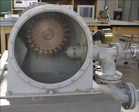
francis hydro turbine
It is a reaction turbine, in which water moves as in a pressure pipe. In fact, thanks to the adjustable nozzle blades, water is carried to the fixed blades rotor, to which it gives energy without coming into contact with the external air. In this type of turbine the water flow is almost always radial while the outlet is axial. FRANCIS turbines are used for water heads from 10 to 350m
FRANCIS turbines

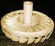
kanplan hydro turbine
They are reaction turbines and they are divided into two types: double (true KAPLAN) or single (semi-KAPLAN) regulation. In the first type both the rotor and the nozzle blades are adjustable. In the second type only the rotor blades are adjustable while the others are fixed. The possibility of adjusting the nozzle and the rotor blades allows one to regulate the functioning of the system according to the flow rate and the water head. In case of constant flow rate the turbine can also be formed by fixed blades to reduce costs. KAPLAN turbines are used for water heads from 2 to 20m.
kaplan hydro power turbine

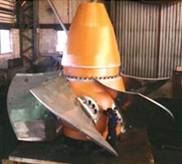
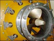
bulb turbine
It is a reaction turbine and it is similar to the submerged part of a big outboard motor. It is specifically used to exploit the wave-motion of the tides or the submarine currents. The rotor of the BULB TURBINE derives from the one of the KAPLAN TURBINE. The generator and the multiplier are contained in a waterproof case immersed in the water.
bulb turbine

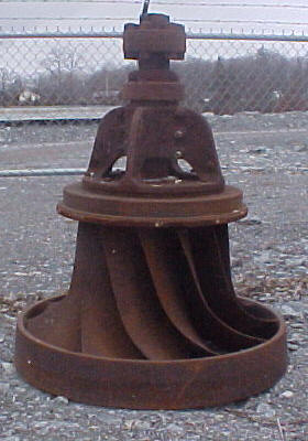
screw turbine
The main characteristics of this technology are the following ones:
use of grids with big holes thanks to the capacity of the Archimedean screw to accept alluvial material and waste of big dimensions;-no combs and therefore no production of waste to be disposed of;-perfect compatibility with fishes;
low costs of the plant and its management. Archimedean screw turbines are used for water heads from 1 to 10m and water flow rates from 0,5 to 5,5 m³/sec. The most important characteristic of these turbines is that they continue to function also with minimum water flow rates. Therefore, they are very proper for irregular water quantities.